
01 / Operational Ecosystem
A mission architecture, not a single screen
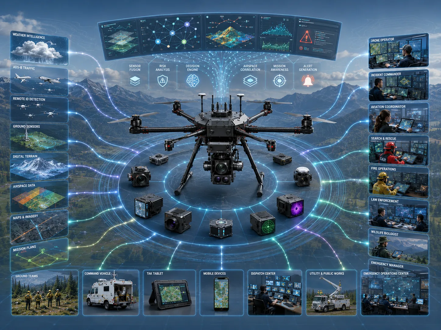
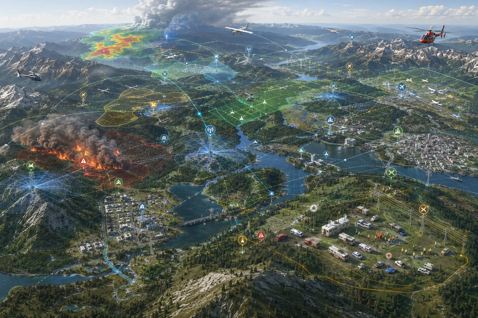
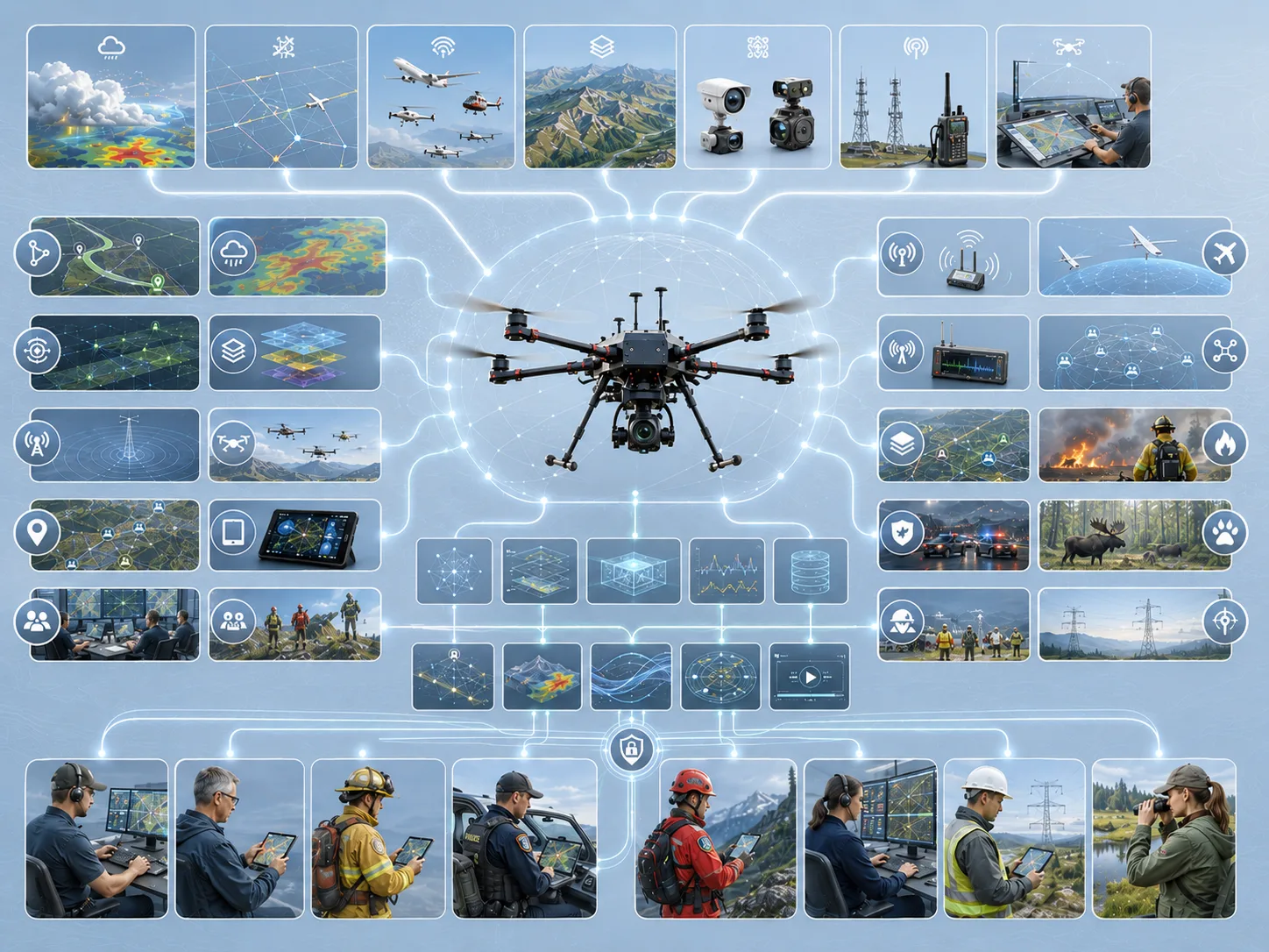
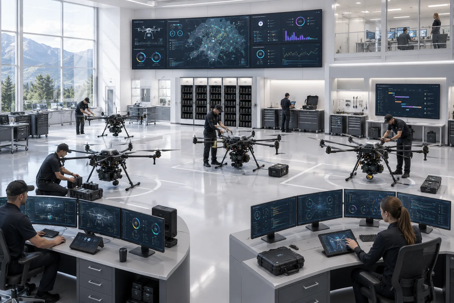
ARS technology is framed as an ecosystem connecting aircraft, sensors, decision-support engines, TAK-oriented interoperability, and role-specific displays.
Technical visual
Technology
ARS technology spans sensing, fusion and reasoning, decision support, and mission displays — engineered to work as one system while remaining interoperable with the tools first responders already trust.
Interactive Technical Story
Select each stage to move through the operating model, platform stack, mission pipeline, sensor fusion, advisory engines, TAK integration, communications, monitoring, common picture, and lifecycle.
Architecture stages
01 / Operational Ecosystem
ARS technology is framed as an ecosystem connecting aircraft, sensors, decision-support engines, TAK-oriented interoperability, and role-specific displays.
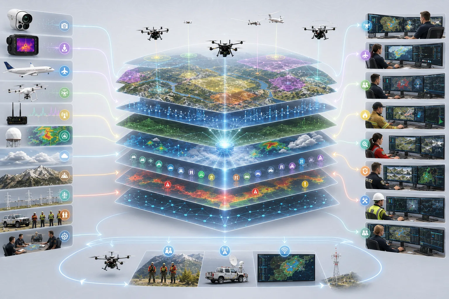
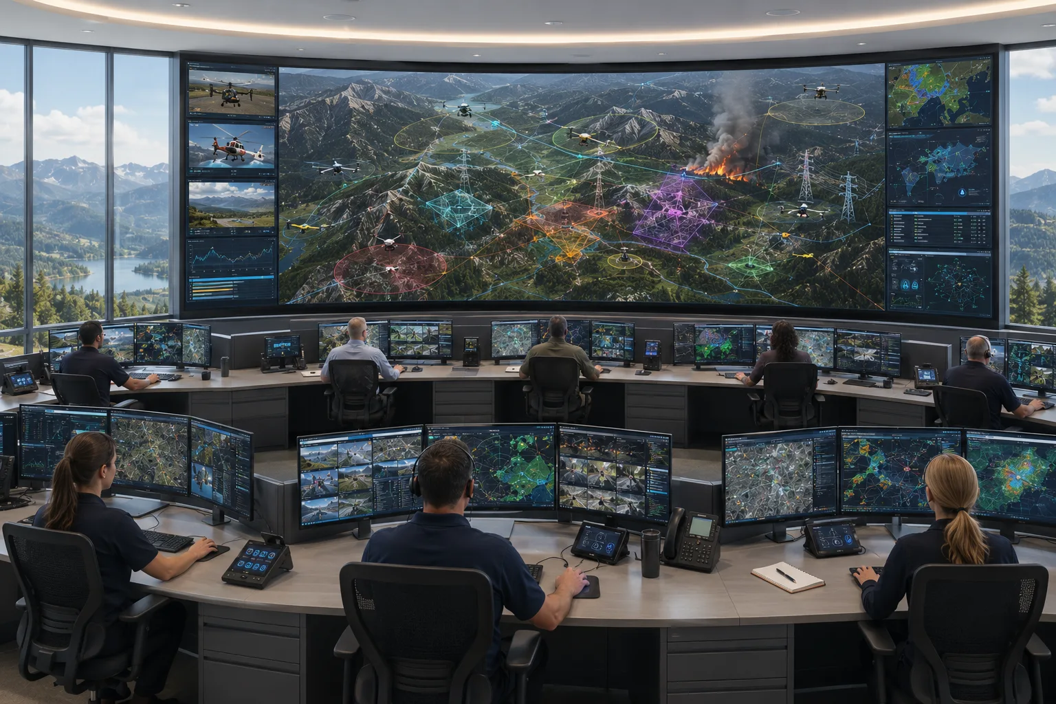
Concept diagrams of the intended architecture; they do not describe the current system.
Large-Format Diagrams
These visuals remain conceptual, but they give technical reviewers a clearer way to understand how ARS is organizing the platform.
01 / Operational Ecosystem
ARS technology is framed as an ecosystem connecting aircraft, sensors, decision-support engines, TAK-oriented interoperability, and role-specific displays.
Technical visual
02 / Platform Technology Stack
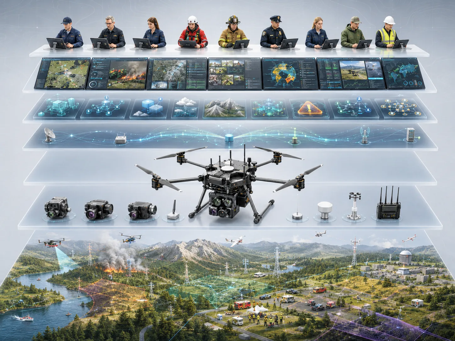
The platform stack visual organizes sensing, onboard compute, data fusion, advisory logic, and the operator-facing display layer.
Technical visual
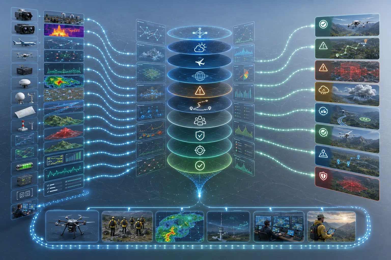
03 / Mission Intelligence Pipeline
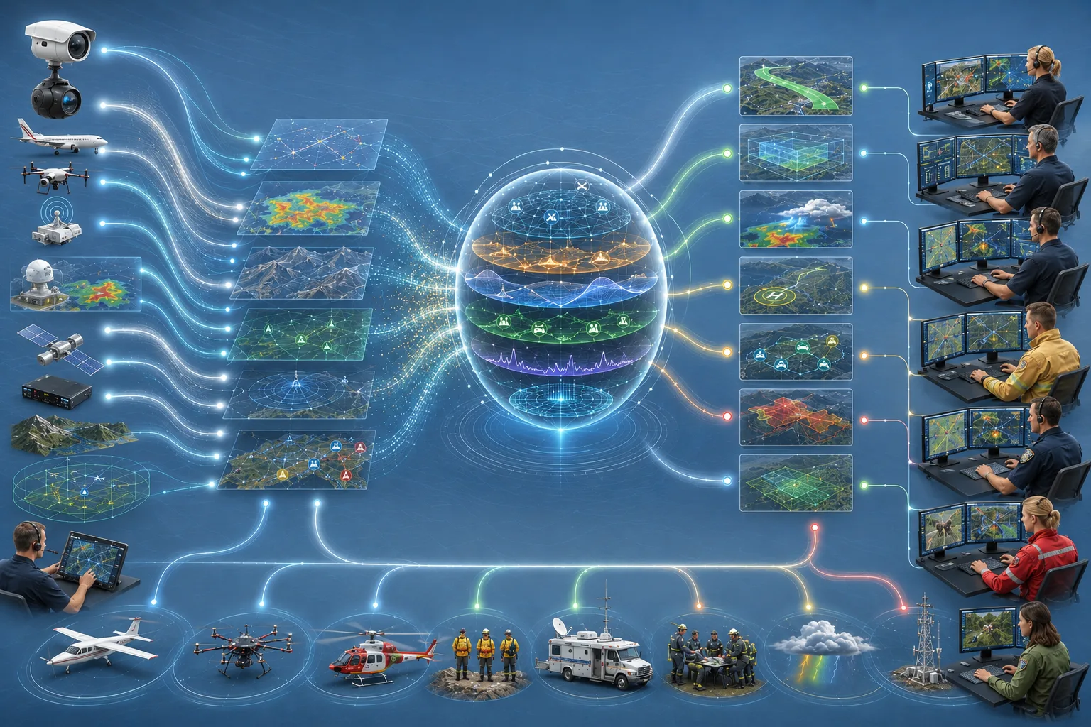
The intelligence pipeline shows how mission evidence can move from raw sensor input toward explainable operator context.
Technical visual
04 / Sensor Fusion
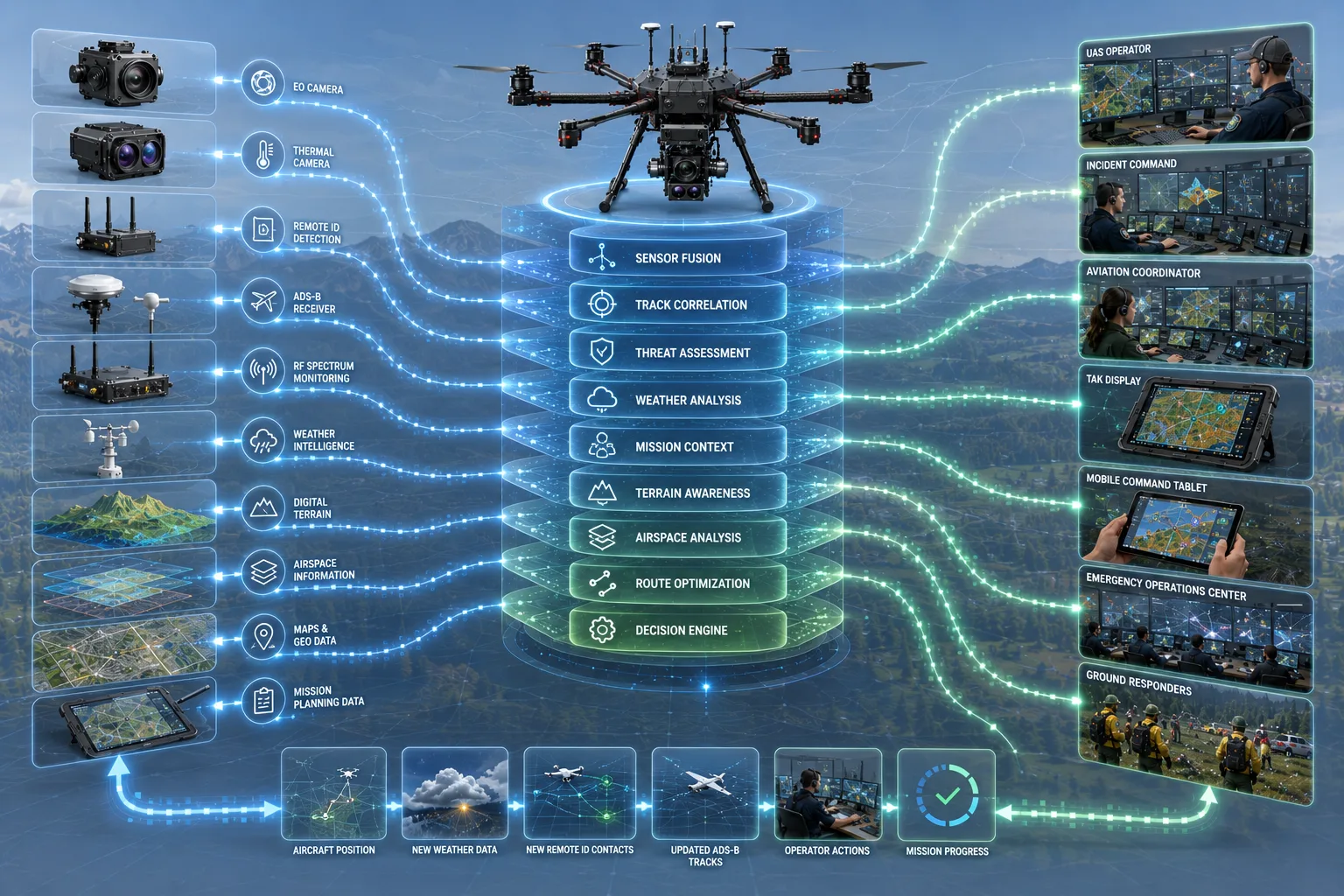
Remote ID, ADS-B, RF spectrum activity, thermal data, GPS reference, and flight telemetry are treated as evidence sources that can reinforce or challenge each other.
Technical visual
05 / Decision Engine
ARS decision-support concepts are designed to explain why an advisory exists. Weather and planning engines recommend and inform; they do not issue flight commands.
Technical visual
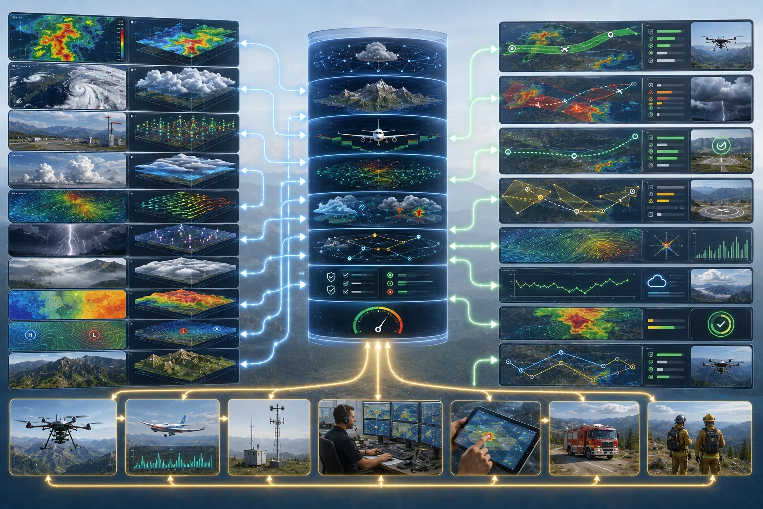
06 / Weather Decision Engine
The weather engine visual supports translating aviation-relevant conditions into operator guidance while keeping final decisions outside automation.
Technical visual
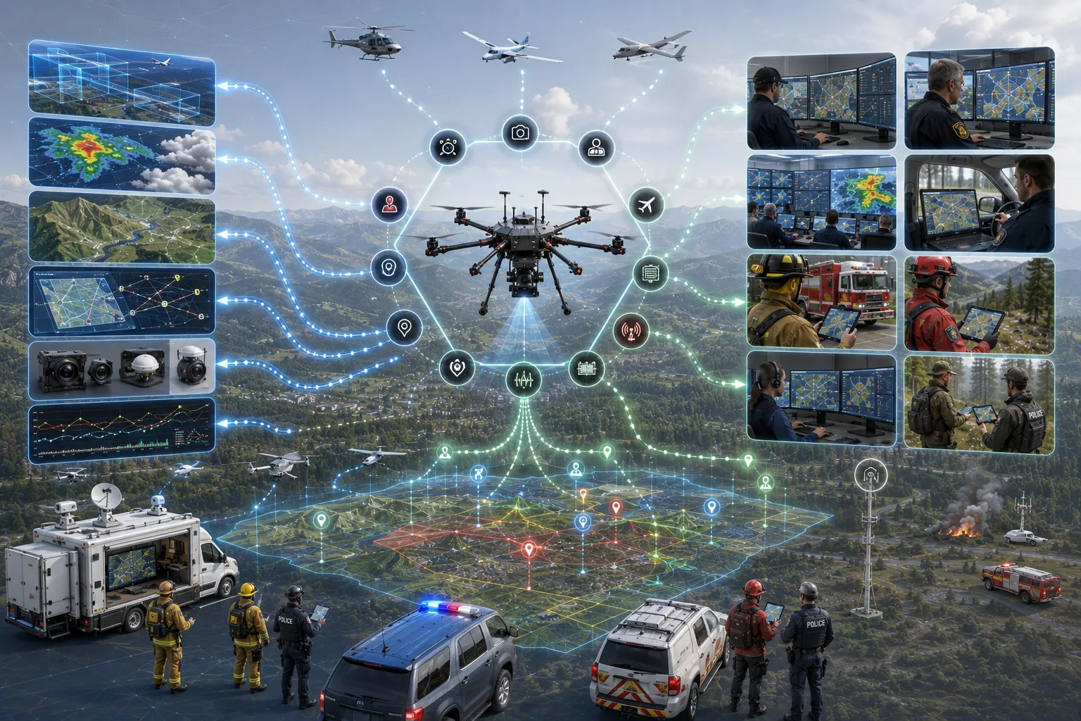
07 / TAK Integration
TAK and Cursor-on-Target integration are first-class architecture concerns so ARS concepts can fit into familiar shared operational pictures.
Technical visual
08 / Communications Network
The communications network visual connects the platform to field responders, command vehicles, and mission display environments.
Technical visual

09 / Persistent Airspace Monitoring
Persistent monitoring is presented as a concept direction for regional awareness, not as a deployed surveillance capability.
Technical visual
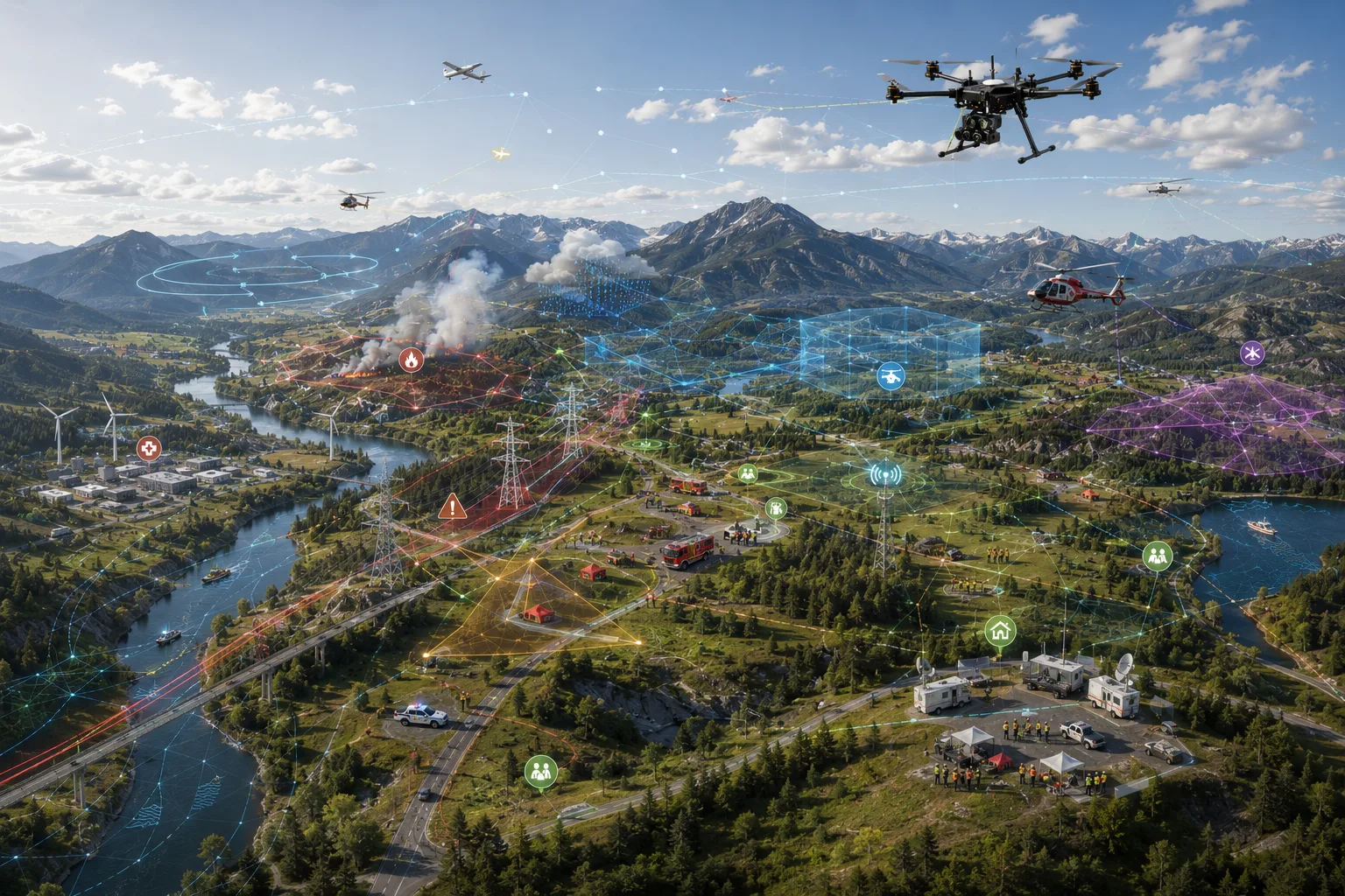
10 / Common Operational Picture
Operators, aviation teams, and command staff need different levels of detail. One data model can support multiple role-specific views.
Technical visual
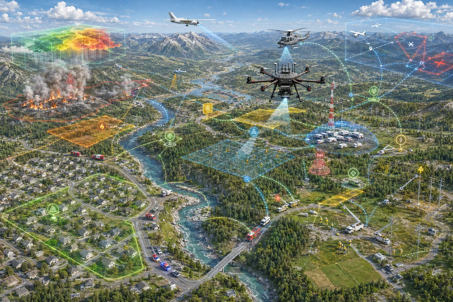
11 / Mission Lifecycle
The lifecycle view connects planning, launch, detection, sharing, and review, including roadmap concepts like after-action event logging.
Technical visual
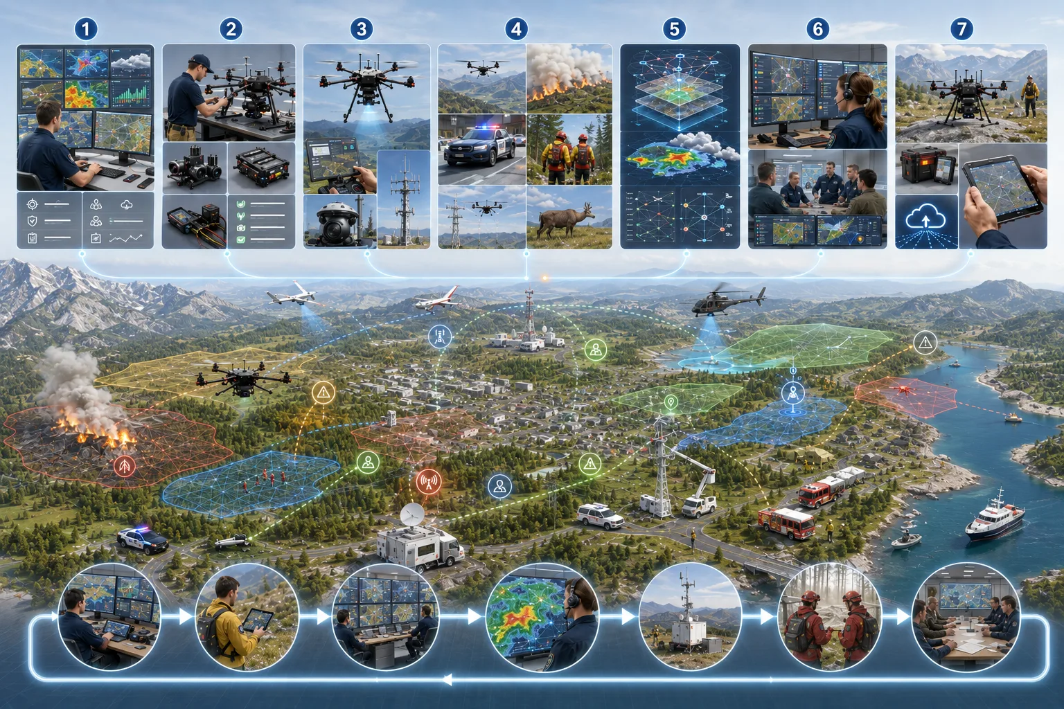
Supporting Architecture Views
These supporting assets fill out the technical library without overloading the primary architecture narrative.
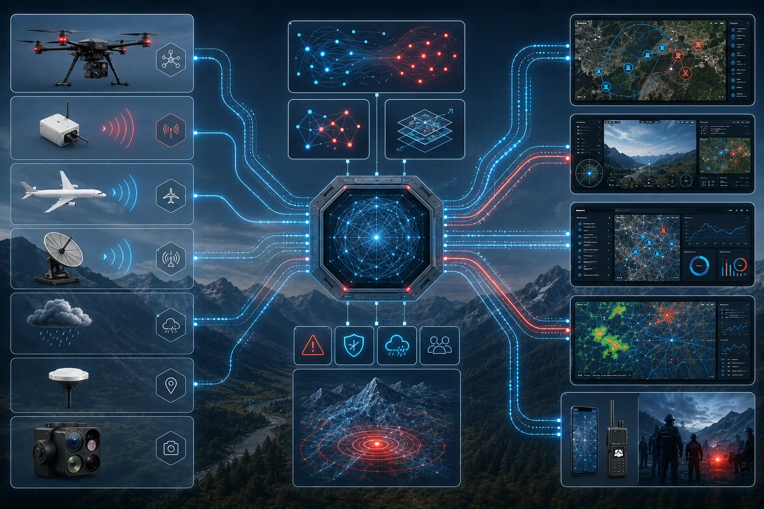
diagram
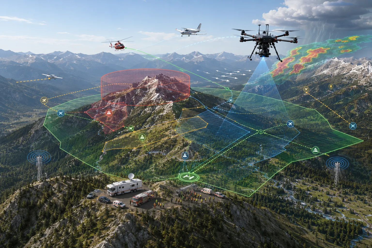
diagram
diagram
diagram

diagram
diagram
diagram
diagram
Airspace Awareness
ARS sensor payload technology is designed to detect and cross-reference multiple independent signal types into a single track picture with plausibility checks. Cross-sensor correlation is a design objective; today each sensor feed is handled separately.
Wi-Fi beacon Remote ID reception designed around the ASTM F3411 broadcast standard, exercised on the bench against ARS test transmitters. Bluetooth reception is a design objective; hardware is not yet selected.
1090 MHz Mode S/ES reception for awareness of cooperative traffic nearby, exercised on a bench rig. 978 MHz UAT reception exists in payload software but no live UAT traffic has been decoded, and it is not part of the current aircraft platform.
RF energy detection is implemented in payload software and thermal capture has been exercised on a bench unit; neither is demonstrated end to end, and RF detection range and false-alarm rates are not characterized.
Payload software is designed to flag tracks that look implausible or inconsistent; it has been exercised against ARS bench transmitters, not real aircraft.
Checking position integrity against an independent GPS reference is a design objective, not a demonstrated capability.
The platform direction favors established, field-serviceable components and rapid iteration.
A passive, advisory-only engine designed to translate aviation weather sources into plain go/no-go guidance for UAS operators. The engine is implemented and tested as software; it is not deployed on the aircraft and has not been run with live weather data. Live network access remains gated.
A planning engine concept built on published search-and-rescue research, intended to support mission planners rather than replace their judgment.
How ARS Validates
ARS's approach is for technology to move through structured internal test programs before it is described as validated, including simulation-first development and adversarial hardware-in-the-loop scenarios as the program matures.
Planned hardware rigs are intended to exercise abnormal and adversarial signal conditions.
Core software is designed with explicit safety limits and bounded authority: decision-support functions are advisory-only, the operator stays in command, and the few automatic responses are narrowly defined return-to-launch commands.
TAK/CoT output is treated as a core integration surface, not a decorative export path.
We're glad to walk your team through architecture, current validation status, and what's still on the roadmap — in plain terms.